Embedded Files

Make and Attach the Connecting Rods
Make and Attach the Connecting Rods

The first step is to create an attachment point for the top of the displacer shaft. The music wire is very stiff and difficult to work with in tight places, so I prefer to not bend the top of the displacer shaft. I make the top piece from soft craft wire that is easy to form. For this application I formed the hook shaped wire on another piece of music wire, then slipped it off and placed it on the displacer shaft. It is held in place with a small drop of epoxy. If I ever need to, I can disassemble the pieces to take it apart and work on it.

I use the same soft craft wire to make connecting rods for the drive piston and for the displacer. The displacer connecting rod has a “Z” bend in it. This is to simplify the adjustment process. If the shaft needs to be adjusted in length, simply grab the middle of the “Z” and give a slight twist to make the shaft slightly longer or shorter.

The shaft connecting the drive piston to the crank shaft does not need to have the “Z” twist because it can be adjusted by moving the nuts up or down on the bolt that holds the piston together.

Assemble the Engine
Assemble the Engine
Secure the lid to the pressure chamber body by pressing it into place. Do not bang on it with a hammer. Pounding with a hammer will dent the lid and cause a leak. If you feel it must be tapped into place, put a block of wood over the seam and tap the wood lightly with a hammer until the lid is seated all the way around.
Attach the displacer connecting rod and adjust it so that the displacer does not touch the pressure chamber top or the pressure chamber bottom.
Attach the connecting rod from the drive piston to the crank shaft. Adjust the length of the connecting rod so that the piston can move freely. It should not go down low enough to pull the fabric of the diaphragm completely tight. And it should not go high enough to extend above the top of the drive cylinder. It should have about 1/4” of travel from top to bottom.
Make a Stand
Make a Stand
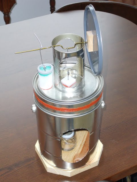
The stand that is pictured here was made from another paint can. (But you can get quite creative if you like. The video of the first running of this engine shows it perched between two soup bowls.) The paint can stand works well. The top is open because the lid from this can was used to make the flywheel. A large hole is cut in one side of the can. The hole does not extend all the way to the top of the can. This is so the hot air from the candle will be trapped in the top of the chamber. The candle used in these illustrations is s liquid wax candle. It is not quite as hot as a wax candle, but it burns very clean and will last for about 24 hours of burn time if you don’t modify it. If you want a larger flame you can pull the wick a little higher. The instructions on the candle advise against this, so be careful.
Fire It Up!
Fire It Up!
Lubricate the crank shaft at every point where it comes in contact with another piece of metal. Use light 3-in-1 oil. Place a drop of the same 3-in-1 oil on the displacer shaft. This will lubricate the shaft as it passes in and out of the gland, and will also help prevent pressure leaks through the gland.
Light up the candle and place it in the stand. Put the engine on top. Let it warm up for about 30 seconds and then rotate the flywheel to start the engine.
The direction of rotation is determined by the 90 degree offset between the displacer and the drive piston. The displacer always moves ahead of the drive cylinder. Rotate in the direction that makes the displacer reach the top 90 degrees ahead of when the drive cylinder reaches the top.
The engine will probably need to have the flywheel balanced before it will run continuously. If your engine tries to run but stops, add a small weight to the flywheel. I use a dime and a piece of tape as my counterbalance. As you observe the rotation of the flywheel you may see that it stops and gets stuck at the same place every time. Tape a dime to the flywheel about 15 degrees forward of the top of the wheel when it is in this stopped position. This is the location where the weight will do the most good to pull the flywheel through this position. It will probably end up being on the opposite side of the flywheel from the displacer crank shaft. Lifting the displacer takes a little work, and a well placed counterbalance will make this a simple task for the engine.
You can place a few ice cubes on the top of the pressure chamber to increase the temperature differential. This may make it easier to adjust the engine for the first time. After the flywheel is balanced and the connection rods are properly adjusted it will probably run with no ice.
Afterthoughts
Afterthoughts
I can hear the bottom of the pressure chamber flexing as this engine runs. That type of popping is called "oil canning". This could be prevented by creating an "L" shaped beam of scrap tin and attaching it to the bottom of the pressure chamber with solder or with JB Weld high temperature epoxy. Also, the displacer could be made larger if it were to be installed during the assembly of the pressure chamber rather than through the lid of the paint can. A larger displacer would increase the swept volume and decrease the dead space inside the motor.
Videos
Videos
Page updated
Google Sites
Report abuse